
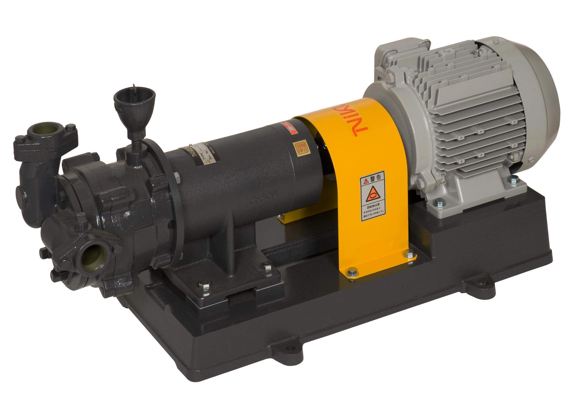
Water_Ring_Vacuum_Pumps
Base-mounted_model
Ferrous, small size
Water_Ring_Vacuum_Pumps Base-mounted_model
LVF
Eliminates trouble caused by drawing in mist, wet gas or steam.
Applications
General industriesSemi-conductor industry
Chemical industries
Vacuum exhaust equipment
Vacuum conveyer
Medical application
Paper and pulp industry
Agriculture community waste water treatment collection
Land subsidence acceleration, Vacuum filling, Vacuum cleaning, Vacuum casting
Features
Liquid Ring Vacuum pumps are capable handing gases containing mist and steam without troubles.No metal-to-metal contact for internal parts casues long lifetime opearation.
Suitable for sucking and compressing explosive, flammable and corrosive gases.
Outstanding power consumption saving due to high efficiency fundamental design.
Liquid ring construction assures gas leak free operation and effective compression, appropriately for valuable gases transferring applications.
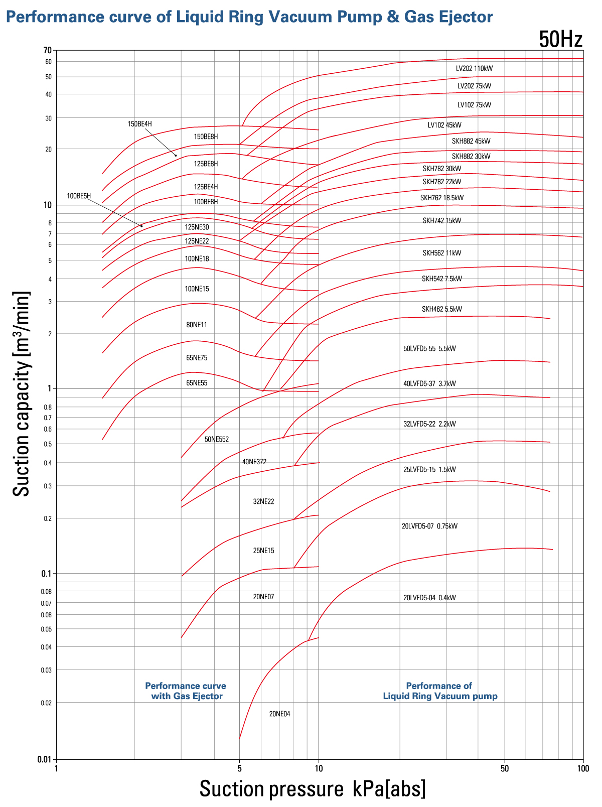
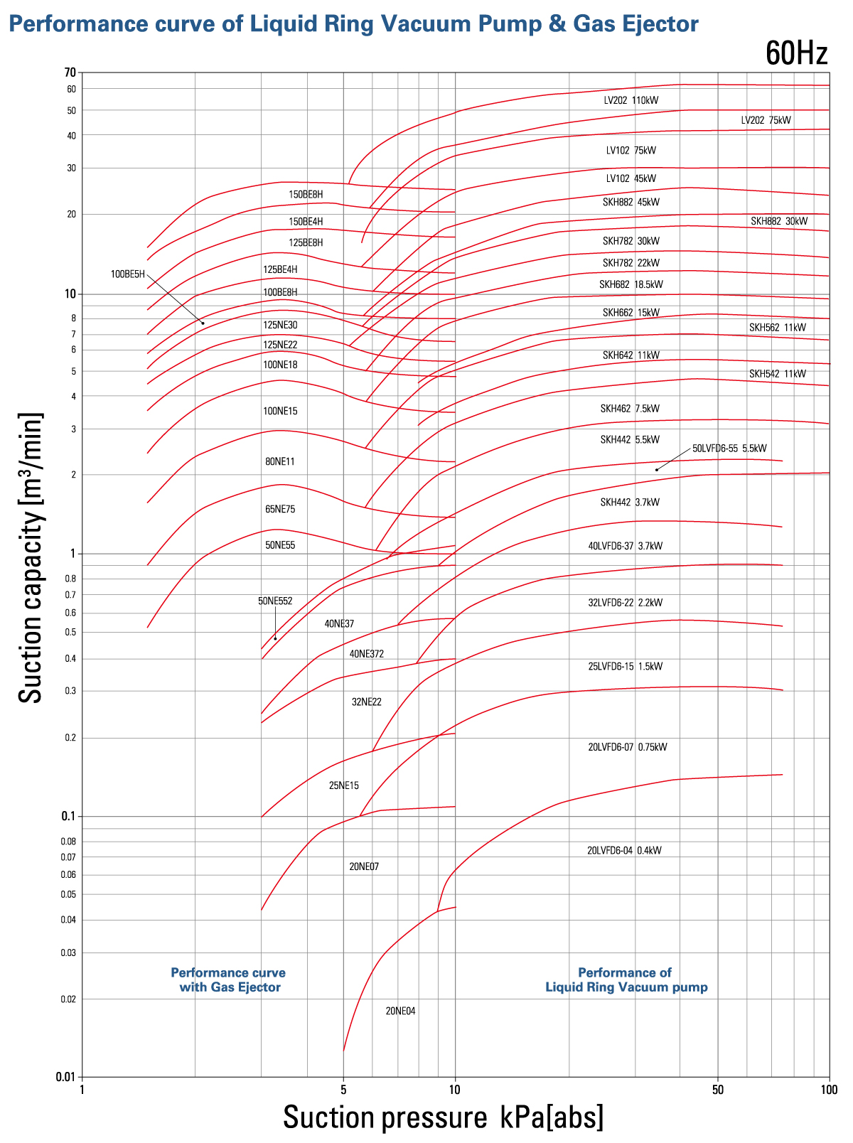
Performance
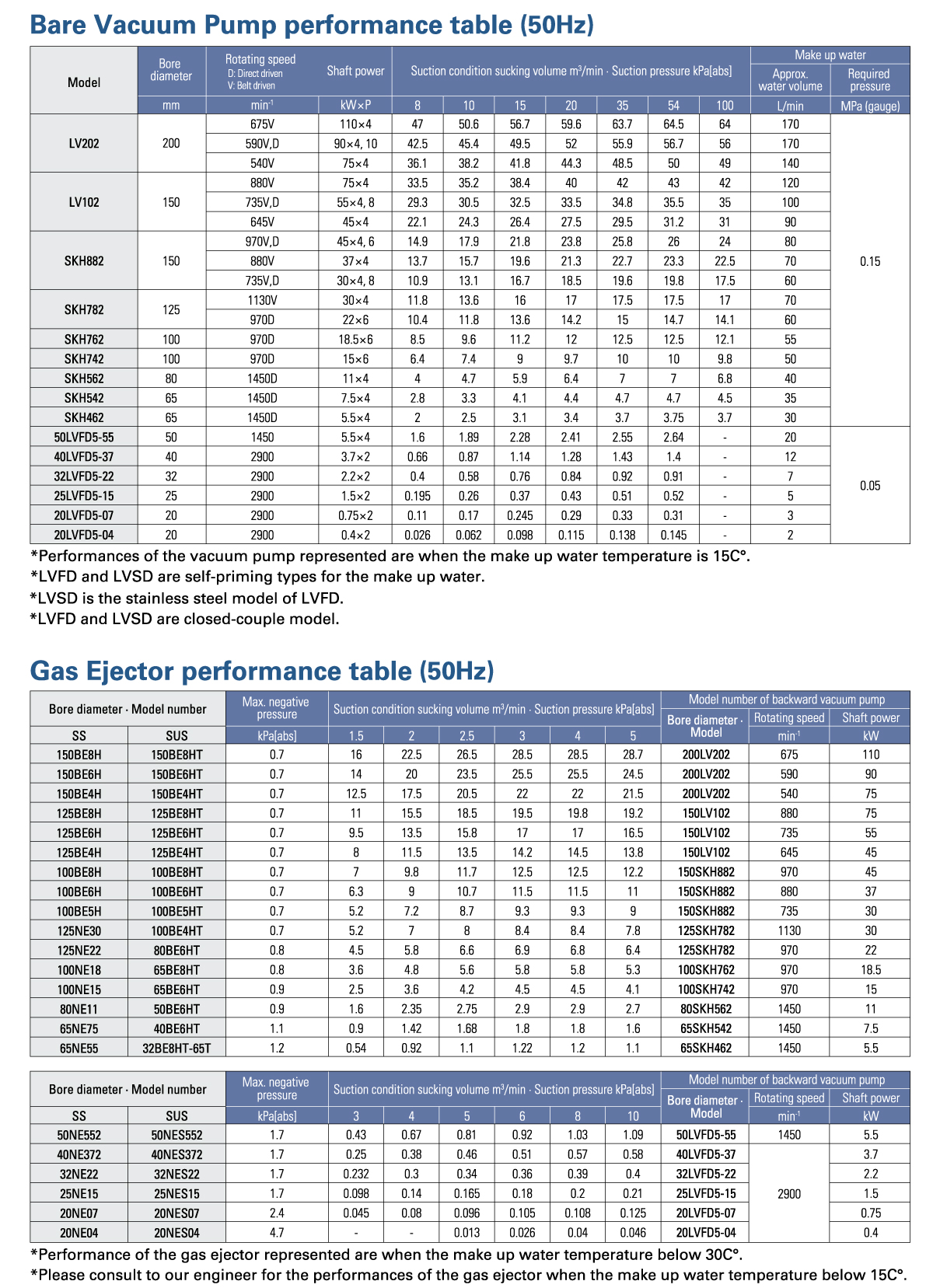
Specification Data
Dimensions

Dimension Table
By installing the gas ejector,
performance stabilizes at the high vacuum range
Liquid Ring Vacuum pump with the gas ejector
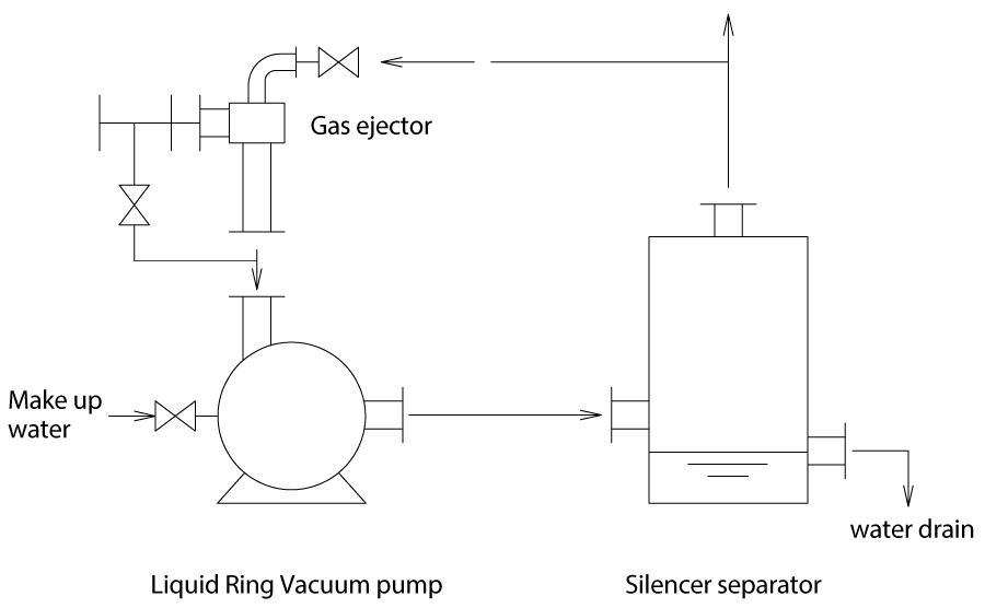
When the water is used for the operating liquid, cavitation occurs round 8kPa(abs) if the water temperature reaches at 30°C. However, by installing the gas ejector at the suction of the liquid ring vacuum pump, it will operable around 1.3~2kPa(abs). In this case, the operating pressure of the liquid ring vacuum pump achievable around 13kPa (abs) and cavitation does not occur. The gas ejector uses the air of the atmospheric pressure (or the exhaust gas from the vacuum pump) as the motive source. Therefore, there is no need for the separate power source.
In the case where the molecular weight of the drawing gas is higher than air, the suction condition sucking volume will decrease. Therefore, please consult with us.
When higher vacuum than the performance shown in Page 6-9, it is possible to install two gas ejectors in parallel. Furthermore, when vacuum level of 0.05kPa(abs) is required, it is possible by using the mechanical booster pump in parallel. Please also consult with us for this case.
Ejector outline dimension

Gas Ejector dimension table
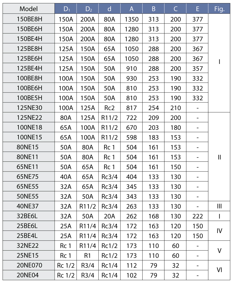
*Flange standard: JIS 10K FF
Threaded connection for the indications in inch for D1, D2 & d dimensions
*Dimension and shape for stainless steel material will be different.
Silencer separator
CT outline dimension (For SKH model and LV102, 202 model)
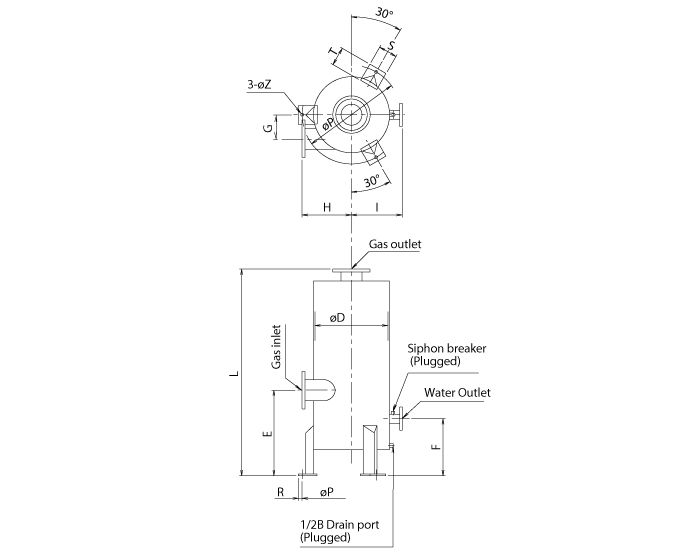
CT type silencer separator consists of the lower part separator and the upper part silencer. When the water is drained from the separator, the flow could be intermittent due to the siphon phenomena. Although this will not have adverse effect on the pump performance, please remove the plug of the siphon breaker.
The piping connection between the pump outlet and the separator inlet shall be flat or sloped downward from the pump to the separator. Please ensure that the length of the connection piping shall be as short as possible.
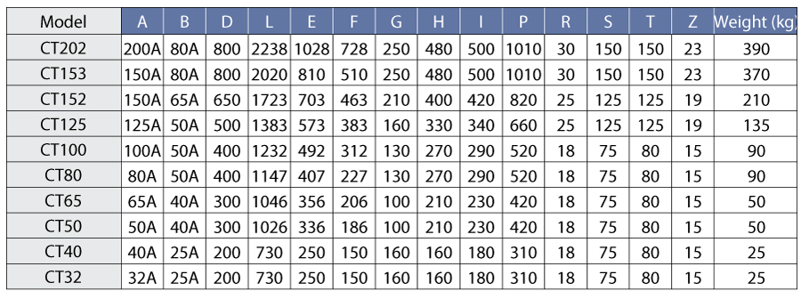
1) Flange standard: JIS 10K
2) Standard material : SGP SS400
3) The connection height (E dimension) is provided to be the lowest height of discharge point among the applicable pumps for CT50 ~CT100.
The connection height (E dimension) is matched to the discharge point of applicable pumps for CT125~202.
4) CT152 is for SKH882 and CT153 is for LV102 respectively.
5) Special dimensions and materials are available upon request.
CN outline dimension (For LVFD & LVSD)
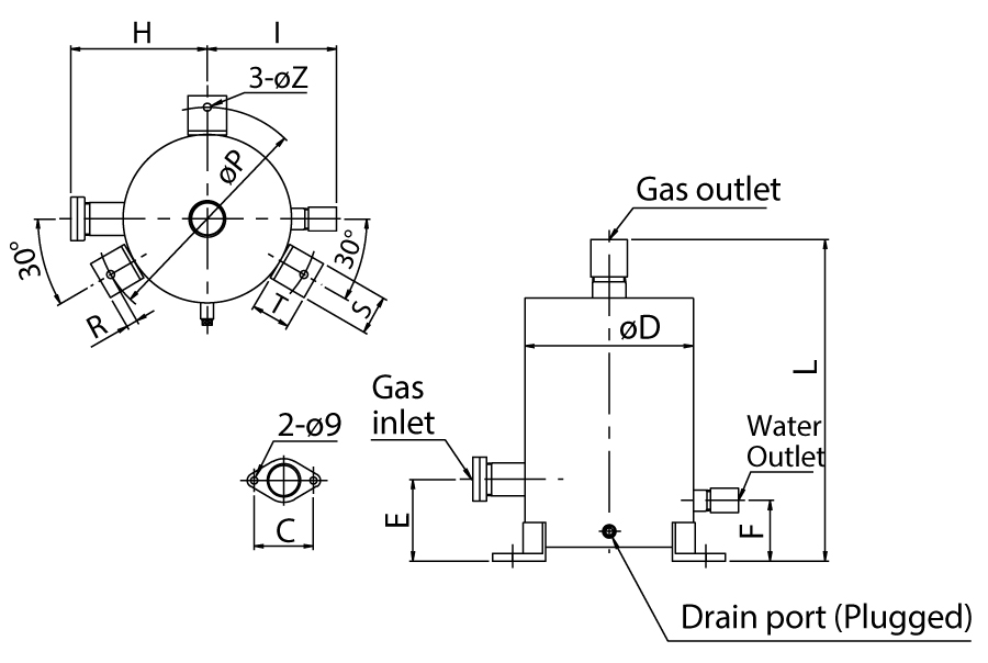
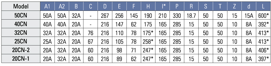
1) Dimension may be slightly different due to threaded connection.
2) Gas inlet and gas outlet of 40CN and 50CN are JIS 5K FF flange.
3) G dimension is the radial-wise eccentric distance between the separator main unit center and the gas inlet A1.
